No products
Prices are tax included


Spare Parts | Option Parts | Manual | Setup Sheets
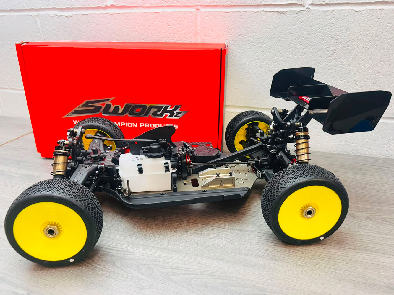
After almost 3 years since the SWORKz S35-4 Evo, the latest iteration of 1/8 buggy from SWORKz is finally here, the hugely anticipated S35-5! The much loved S35-4 Evo is a tough act to follow, which is why SWORKz has taken the best from the existing platform and further evolved and refined the core formula into the new S35-5, which while featuring very similar suspension geometry adds a whole host of wanted features for both performance, ease of maintenance, better reliability and a whole lot more besides.. Lets get into the build and start to appreciate all the effort SWORKz and the race team have made and hopefully share some tips and tricks along the way to help you get the best from your build.
In order to complete the car, as we would expect from any competition kit we will need the following equipment to hit the track:
| S35-5 Nitro | S35-5e Electric |
| .21 Non-Pullstart Engine | 4268 Brushless Motor |
| Tuned Pipe | Electronic Speed Control |
| 2-Channel Radio | 2-Channel Radio |
| 2x High-Performance Standard Servos | High-Performance Standard Servo |
| 2S 7.4v Li-Ion Receiver Battery | 2x 2S 7.4v LiPo (Shorty/Mid-Shorty/Stick) |
| Starter Box | Battery Charger |
| Fuel | Tools (For assembly) |
| Glowstart & Charger | Polycarbonate Bodyshell Paint |
| Tools (For assembly) | |
| Polycarbonate Bodyshell Paint | |
| Air-Filter Oil |
Bag A - Instructions, Decals, Oils & Accessories
Whilst the kit does come with some allen keys, it goes without saying that these should be filed in the bin! Instead we used our trusty MIP Tools to complete the build.
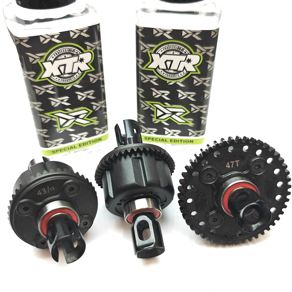
You do also get some silicone diff oil to complete the kit; 15,000, 7.000 diff oils and 600 CPS shock oil. These are perfectly fine to use, but we preferred to build the kit using our XTR Silicone Oils, to ensure we get consistent changes from when we come to tune the car. Rather than the included tub of grease, we also preferred to use our XTR Greases;
The setup was 100% as per the starting setup at the back of the manual on Page 38, with the only exception being we used 500 CPS in the front shocks, 450 CPS in the rear shocks.
Bag B - Front & Rear Differentials / Bag C - Centre Differential
The Front, Centre and Rear HET Differentials remain un-changed from the S35-4 Evo, which is no big surprise as they have been the backbone to the 1/8 SWORKz line-up since the S35-4, offering a generous capacity giving consistent performance. If it ain't broke, don't fix it!
The diffs were built as per manual using the starting setup of 15,000 Front, 15,000 Centre and 7,000 Rear and they went together perfectly as per the manual.
Bag D - Front & Rear Gearbox Assembly
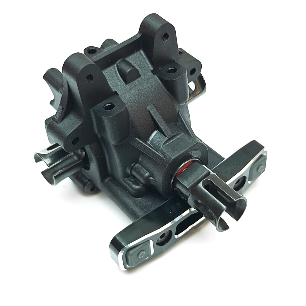
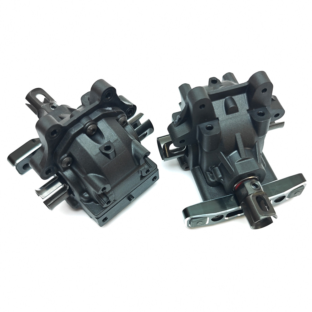
Bad D is where things start to get interesting, as we get to see the all new height adjustable quick access gearbox design. Whilst the height-adjustable feature of the diffs is hugely beneficial, it does make things quite a bit more complicated, at least when your not familiar with it. Once you understand the fundamentals however, and get used to how it works it does become much easier to understand.
In addition to the diff height adjustment, the new gearbox and insert design also allows for a much more horizontal angle of the centre-rear driveshaft, something that has been sub-optimal for a number of years with the older gearbox.
Step 5 & 6
Although not illustrated in the manual, the three pieces that make up the gearbox casing have some cross-sections of excess plastic from manufacturing, which you need to trim them off entirely in order to assemble them.
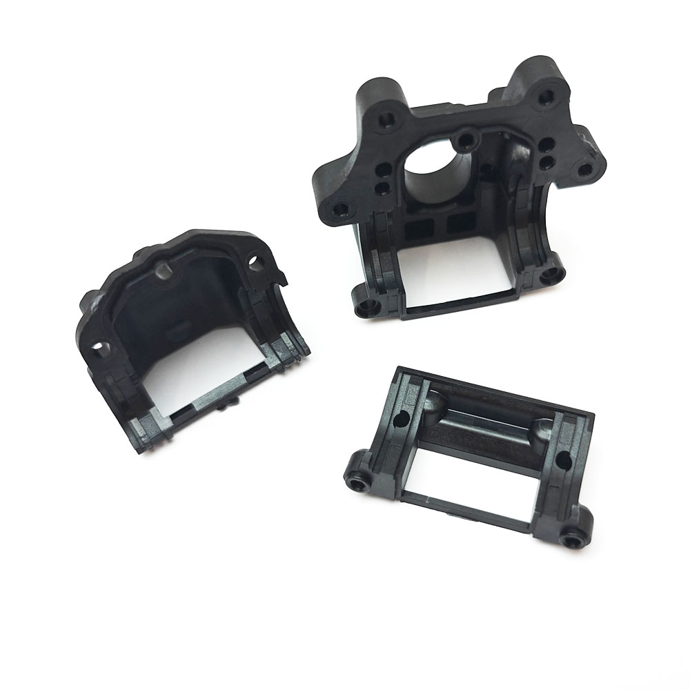
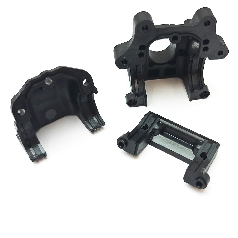
Just before you have to try and get your head around the diff height adjustments, I would strongly recommend installing the front lower part of both front and gear gearboxes BEFORE installing SW338059 and SW338137 B and C Lower Arm Plates, as access to the 2x SW106002 M3x10 BH Screws becomes massively restricted once both the B and C blocks are installed. The manual tells you to install the plates first, but without a ball-ended 2mm wrench or potentially scratching the braces, it can be a bit awkward. The kit features some new lower arm mount plates, namely the F/F, R/F & R/R (A, C and D Plate) to work in conjunction with the new gearbox casings, but the F/R (B-Plate) and Upper Arm Mount remain the same from S35-4 Evo.
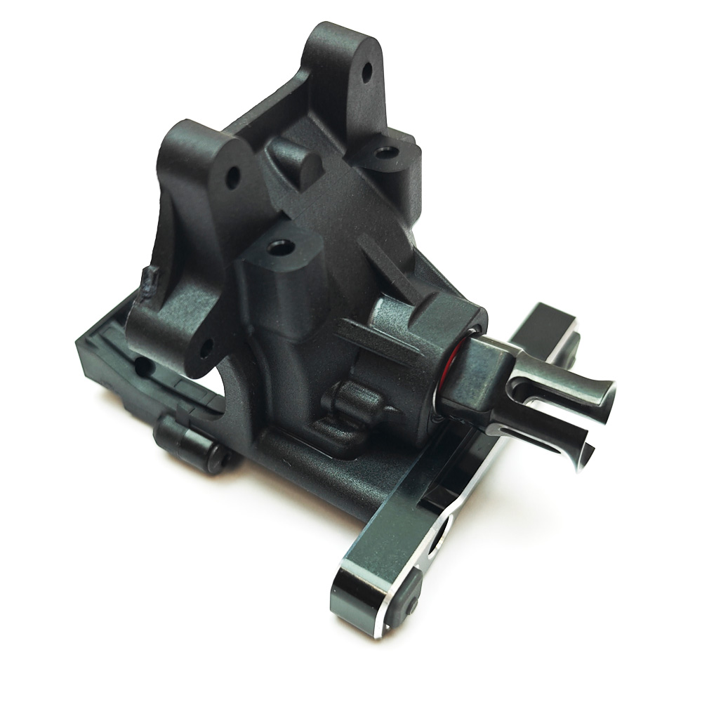
The SW228001DG Bushings required I also found in Bag E - Just in case you are end up in the same boat!
In the manual, just before we start Step 5, there is a full page of instructions relating to the diff height adjustable eccentric inserts for both pinion gear and diff. There is also some really useful information for the process of installing and removing the diffs using the quick-access gearbox design. Please do take the time to familiarise yourself with all of this information before proceeding; its worth your time!
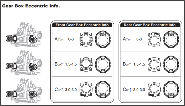
Fundamental Information:
To build the S35-5 with the same diff height as the existing S35-4 Evo, you can easily do so by ensuring it is build in the lowest diff height position, so 0 all round = This will give you. The lowest setting is basically the same, with two additional heights being available to you for tuning; +1.5 and +3.
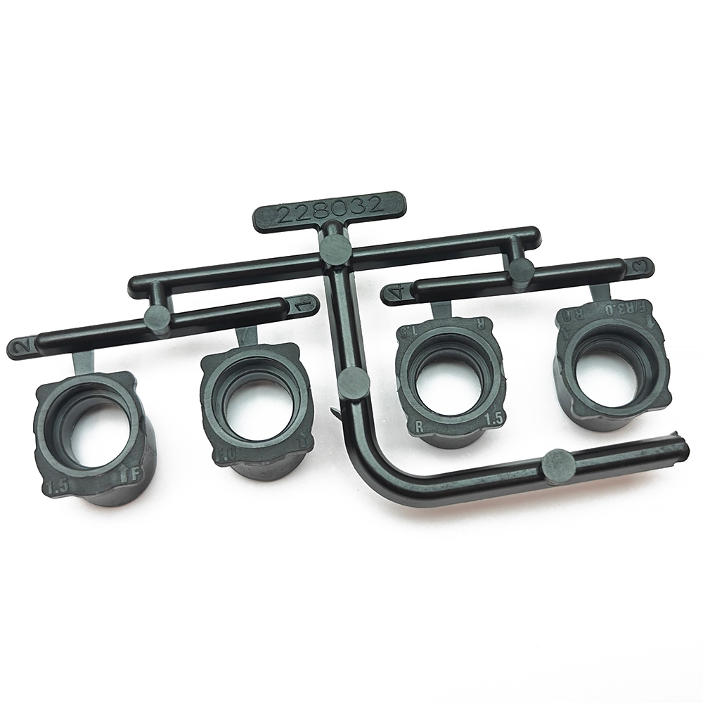
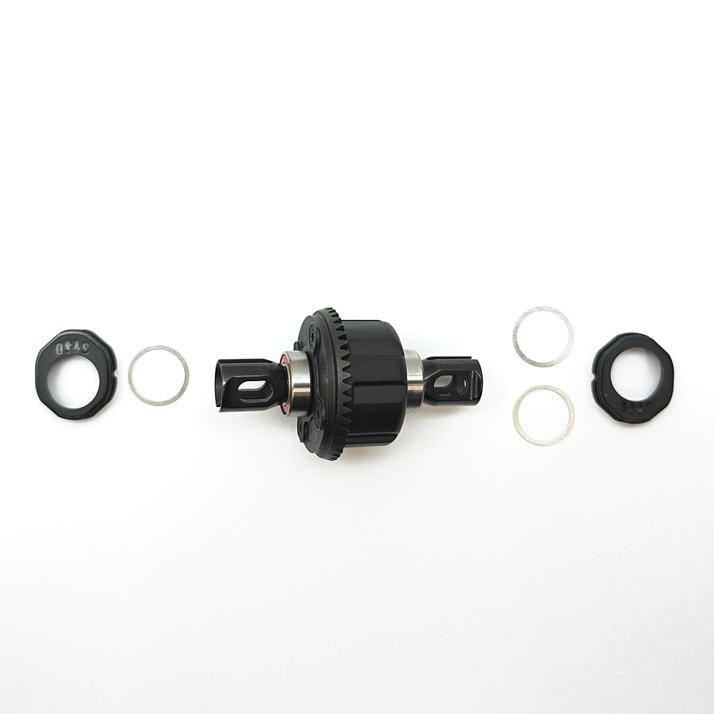
Diff Pinion Inserts (SW228032)
• The arrow should point UPWARDS relative to the adjustment that arrow is next to on the part.
• There are 2x FRONT GEARBOX ONLY pinion gear inserts per parts tree (Part SW228032, #1 - 0/Lowest Height & #2 +1.5/Middle Height) - Arrow up.
• There is 1x REAR GEARBOX ONLY pinion gear inserts per parts tree (Part SW228032, #4 - +1.5/Middle Height) - Can be installed either way, so no arrow for indication.
• There is 1x FRONT and REAR GEARBOX pinion gear insert per parts tree (Part SW228032, #3 - Arrow up Closest to R0 = 0/Lowest Height in rear gearbox. Arrow up closest to F/R3.0 = +3/Highest Height in either front or rear gearbox).
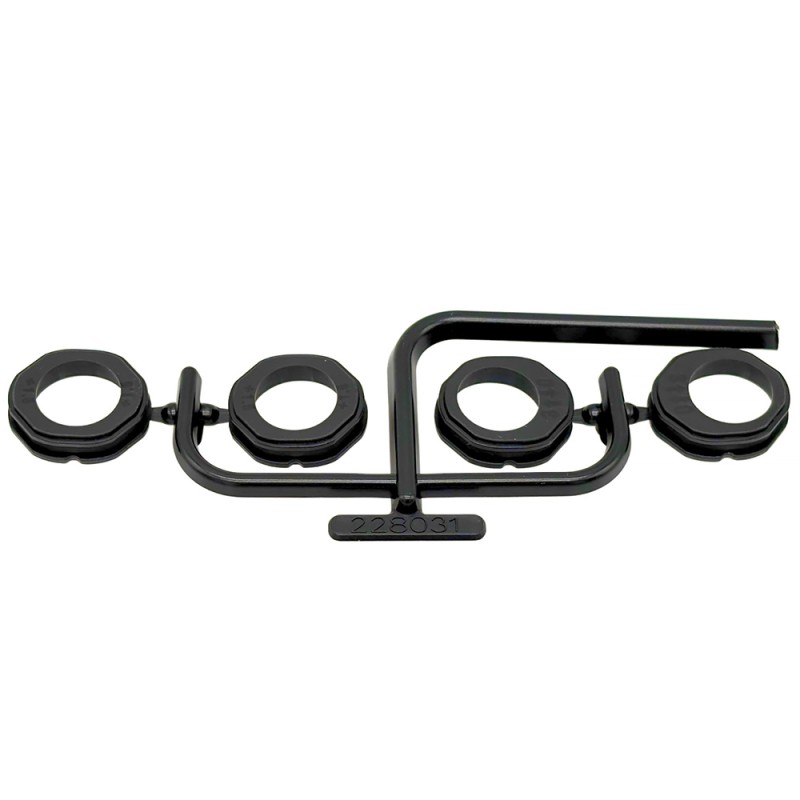
Diff Position Inserts (SW228031)
These are thankfully much simple than the pinion gear inserts!
• Used on both FRONT and REAR diffs
• The arrow should point UPWARDS relative to the numbered adjustment that arrow is next to on the part.
• There are 2x +1.5 inserts per parts tree - Used on either front or rear diff to position it at the middle height setting (+1.5)
• There are 2x 0/+3 inserts per parts tree - Used on either front or rear diff to position either at the lowest height setting (0 - Hole in the insert = down) or highest height setting (+3 - Hole in the insert = up)
• You MUST match the diff pinion insert height to the applicable diff position insert height as per the manual chart on Page 9.
Diff Shimming
The manual specifies to shim both front and rear diffs with 1x SW101018 13x16x0.2mm Shim either side of the diff, which is absolutely fine as a starting point to build the car, and its not likely to cause any issue, but as is the case with diff shimming, the tolerance is small and it will vary from kit to kit. Similarly; once the car has been ran and the diffs bed in, you do need to check and re-adjust. I personally found the manual suggestion had a touch more side-to-side play than I wanted on both of the diffs, so after some trial and error I found that a total of 0.6mm of shims removed all play, without making the diff tight in the gearbox. I ended up using 1x 13x16x0.3mm shim either side of the diff, which was perfect - For this I used our own Answer-RC 13x16.0.3mm shim set - Answer-RC Shims 13x16mm (10x 0.3mm) – 10Pcs
Alternatively, you do get plenty of the SW101018 13x16x0.2mm Shim's in Bag D, so an extra one on either the ring side, or cup side may do the trick for you, but do just check which side the extra shim works best on to achieve the correct diff mesh. It should never feel overly tight or notchy, and should have a slight amount of play between the ring and pinion gear whilst holding one and rocking the other - Similar to how yo would mesh a spur gear and clutch bell/pinion gear.
Bag E - Front Suspension
Step 8
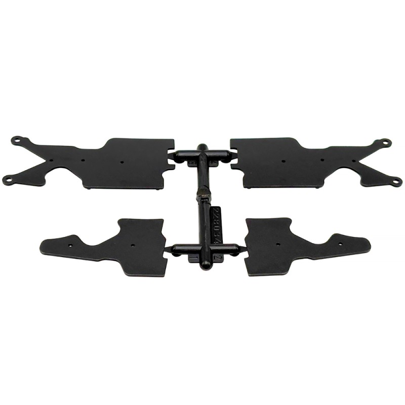
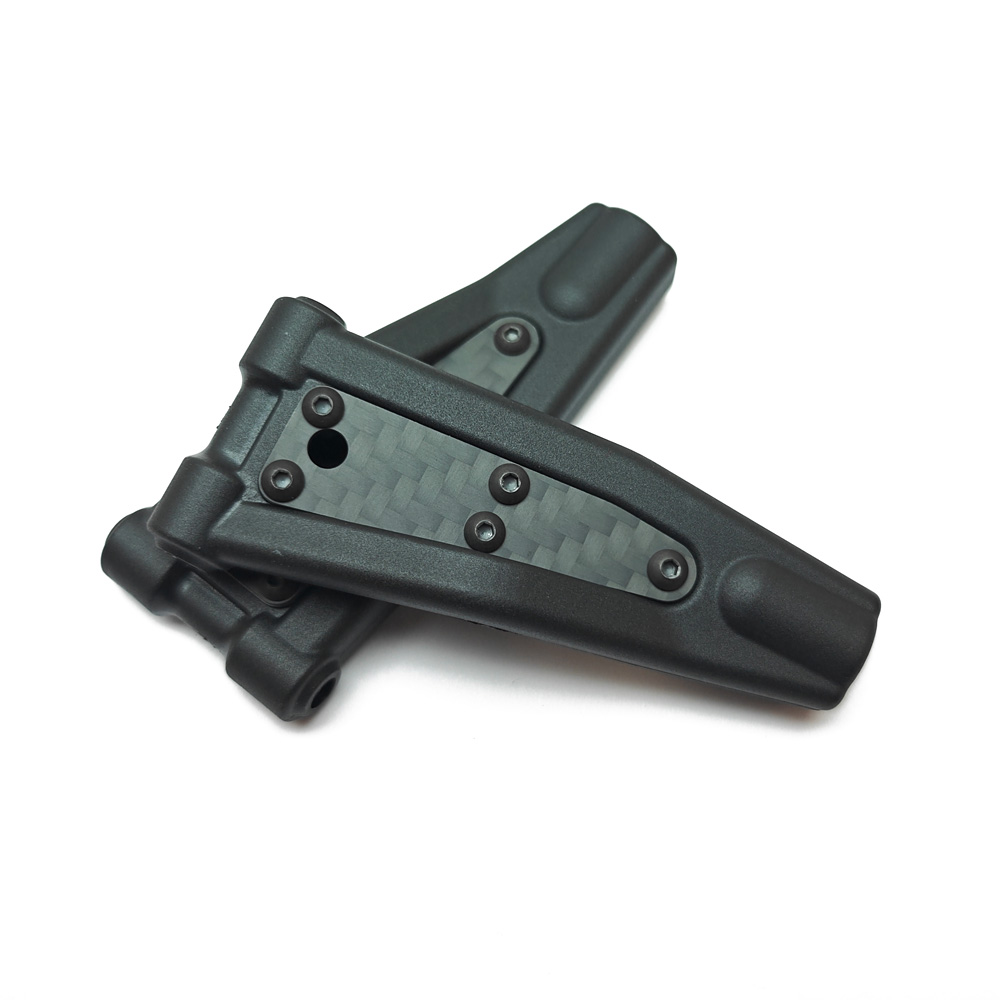
Here we get out first glimpse of the new plastic arm inserts, which really help to neaten off the appearance of the arm whilst minimising the impact on arm rigidity unlike the prior carbon inserts which we've had as an option on the S35-4 Evo. The arms otherwise are 100% the same as the existing S35-4 Evo, so any spares existing customers may have are still usable.
The plastic arm inserts were attached as per the manual using a few small drops of thin cyanoacrylate super glue - We used T-Pro Thin Tyre Glue which worked great, time will tell how well the covers stay in place but they certainly look a lot better and are fully compatible with the S35-4 Evo for customers wishing to retrofit them.
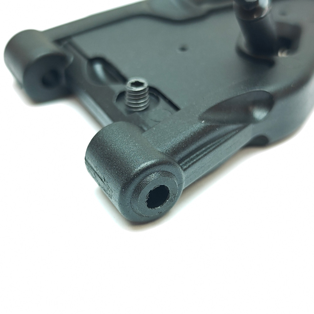
I did find that the SW228005H-F Front/Lower Arms were a little tight within the hinge pin braces once I had fully assembled them in Step 8, which to be honest I have found on a prior build of an S35-4 Evo. They normally wear in, so its not a huge issue, but I did just file them down a little off the backside to ensure they were nice and free once everything was bolted up snug - Loose is fast!
Step 9
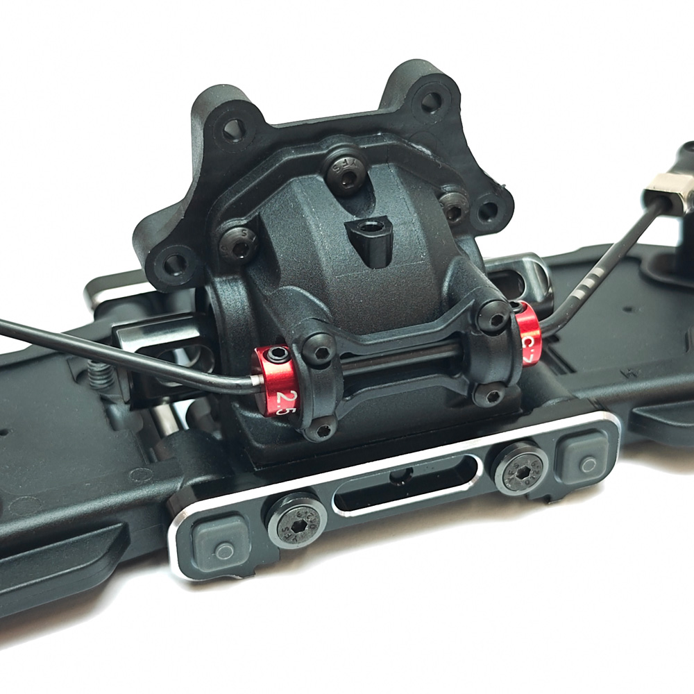
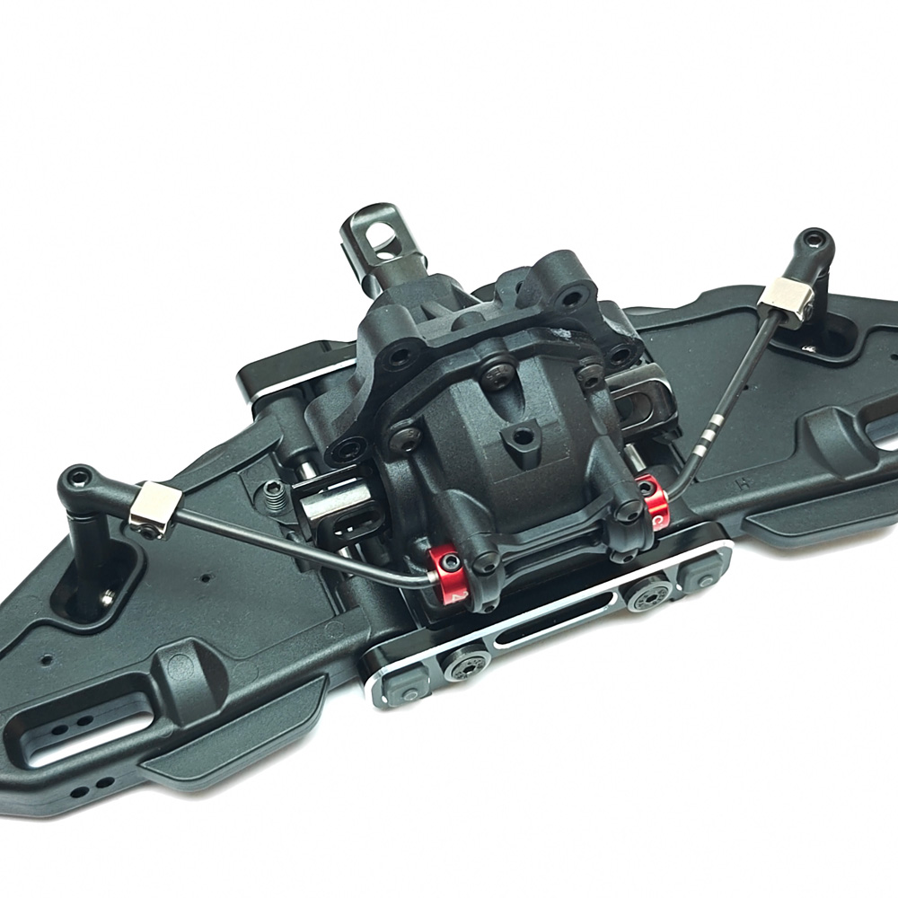
In step 9 we can fully appreciate the new anti-roll bar mounting system using the vibrant red flanged bearing collars. Admittedly I was a bit sceptical of this overly-elaborate design which has become increasingly popular on 1/8 buggies. I've often not seen the benefit on this being a rugged off-road class, but I am now fully converted! This design eliminates ALL of the play from the anti-roll bar, but still allows it to be completely free - Which is only going to be a benefit, increasingly so on higher grip tracks we now widely race on.
One tip during the assembly; I found it much easier to slide the SW116009 Flanged Bearings all the way onto the centre of the anti-roll bar first, and then fit them onto the SW118005 collars once those have also been slid into place in the middle of the bar.
There are some useful indication marks on the anti-roll bar of where to centralise it within the collars, I found this best to do once you had secured the anti-roll bar in Step 10. Just ensure the anti-roll bar is free and not pinched too tight between the collars when you've nipped up those up.
The kit comes supplied with a choice of 2x front anti-roll bars and 2x rear one's; 2.2mm and 2.3mm for the front and 2.6mm and 2.8mm for the rear. It goes without saying that there is a range of optional one's to chose from, available either separately or as part of a front or rear set respectively: SWORKz S35-5 Series Sway Bar Options
Initially we were concerned that to change to an alternative size roll bar, we would have to change the red sway bar holder as well, but this is not the case. The kit includes a 2.5mm front anti roll bar holder and a 3.0mm anti roll bar holder, which is the maximum size of roll bar you can use with either holder. If you wish to install larger than these then you would need to purchase an optional anti roll bar holder. Similarly; the anti roll bar adjustment stud (The part threaded collar that the end of the anti roll bar attaches into with a grub screw) also are available in different diameters, but the standard SW339023 is fine for up to 3.0mm and is fitted both front and rear.
Step 12
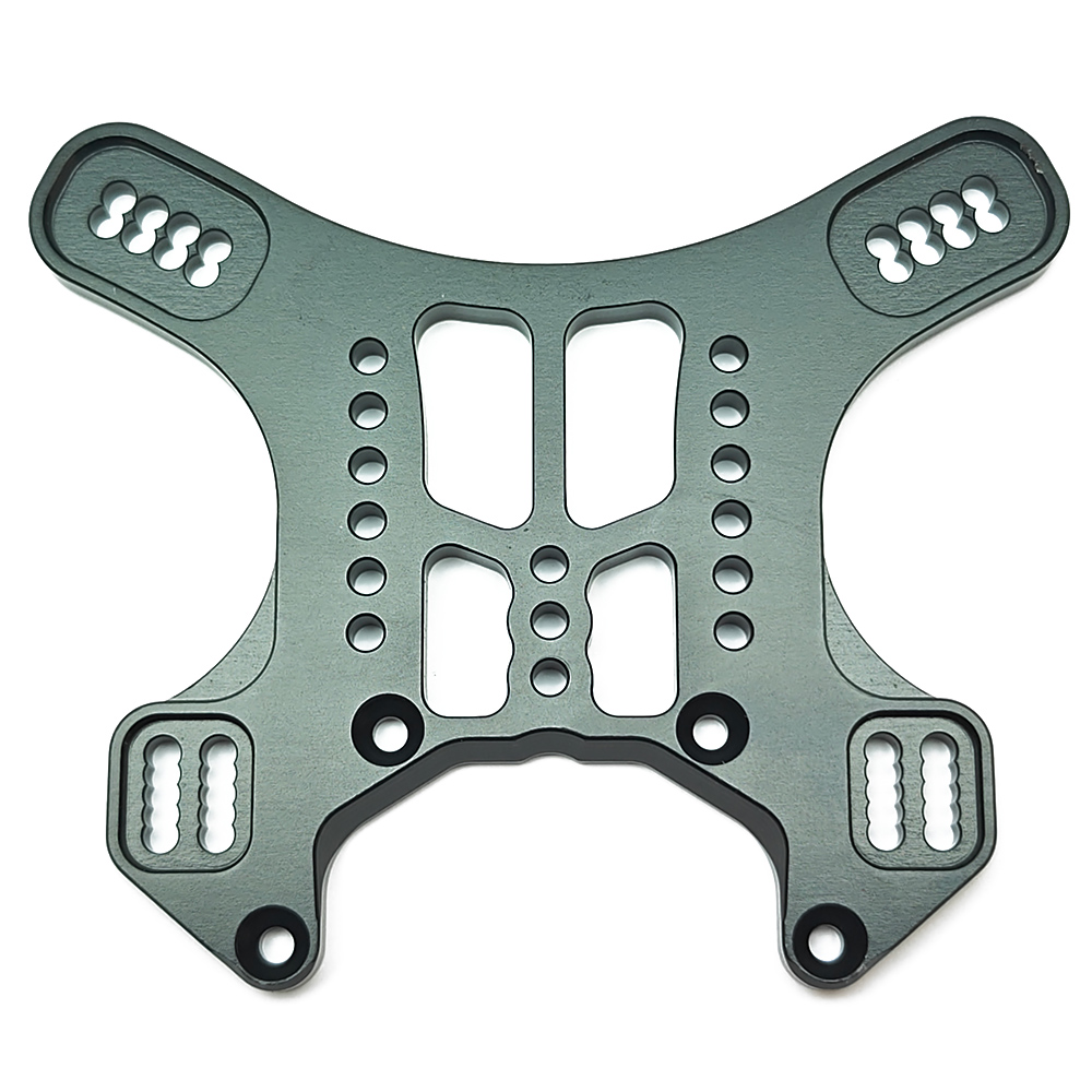
In this step we get to see the new shock towers, which now have an additional set of lower holes to the pre-existing S35-4 Evo towers, giving an additional tuning option to help dial the car in to higher-grip tracks and lowering the centre of gravity. This lower set of holes may best be used with the optional (But also included in the kit) set of lower-profile SW2501121C Shock Cups, which allow for a lower ride height setting with less spring pre-load. The material is said to be stronger than the previous S35-4 Evo towers and has an a harder coating, indicative of the more 'Matt' finish to the tower.
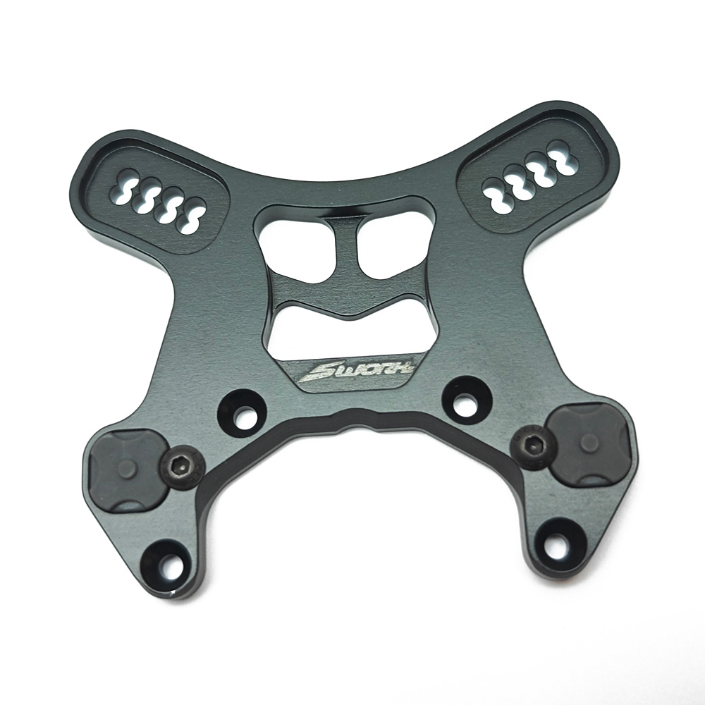
In addition to the bling of the machined aluminium, we also have added bling with the carbon upper arm stiffeners which are now supplied in the kit as standard in conjunction with the LCD front upper arm which was a later option on the S35-4 Evo to offer greater caster angle adjustment
Step 14
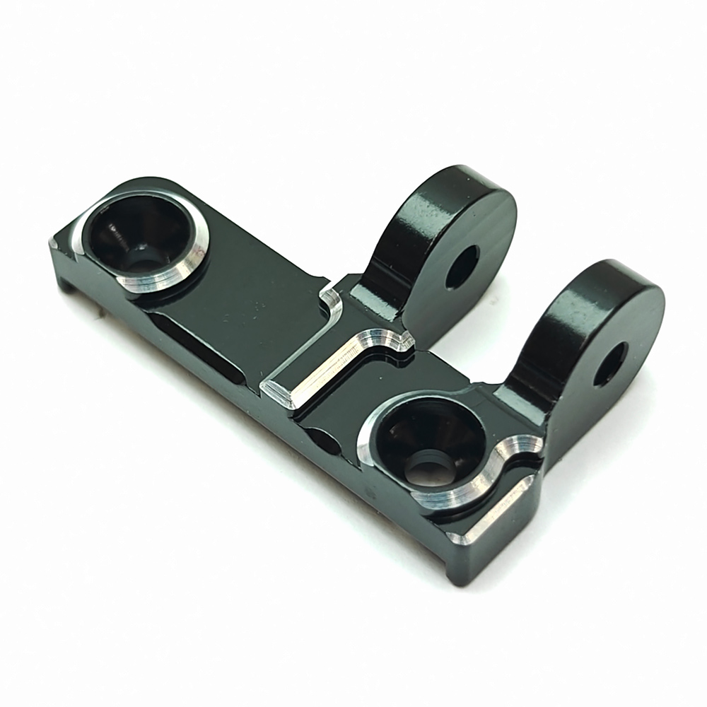
The Rear Shock Tower also has an extra set of lower holes as per the front tower, and we also have a new machined aluminium rear chassis brace mount, which now has black anodising with a classy machined bevelled edge - It's great to see this coming as standard in the kit!
Step 15
Similarly to Step 8 above, I also Dremeled the inside of the SW228015H Lower Arm's to give a slightly amount of place between the C & D Blocks, as once again I did find the movement stiff on the arm once everything was tightened fully. You'll also note that the new R/R Lower Arm Mount (D Plate) , which as standard gives up to 3 degrees of toe-in. As an added option there is also a 3.5 degree toe-in plate available; SWORKz S35-5 Series Rear Lower Toe-In Block (3.5 Degree)
Bag E2 - Steering Assembly
Step 18
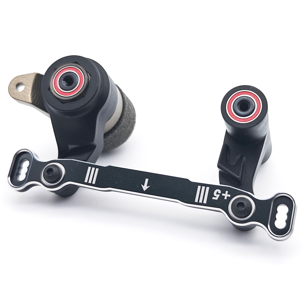
The dreaded servo saver! Probably my least favourite job as I tend to use my fingers to avoid using tools which can damage the finish of the adjustment nut. There still isn't a 'Suggested setting' in the manual, but you do need to wind it on enough to see thread from the servo saver tube. After some trial and error I went to about 2mm of thread showing; which was a struggle! The kit comes with the SW118003H 'Hard' spring, but there is also an even harder option available should you prefer; SWORKz S35-4 EVO series Servo Saver Spring (Hard 2.4)
The rest of the steering assembly is largely all un-changed from the S35-4 Evo, although the S35-5 does now come with a +5 Ackerman Plate as standard, with a further optional +10 Ackerman Plate also available for increased steering; SWORKz S35-5 Series Pro Steering Plate (+10)
I would recommend leaving the 2x SW108003 M3x10 FH Screws slightly loose at this stage, this will make aligning the bottom of the steering posts into the chassis easier when you come to mount the whole front end onto the chassis - Just don't forget to tighten them up once its bolted to the chassis.
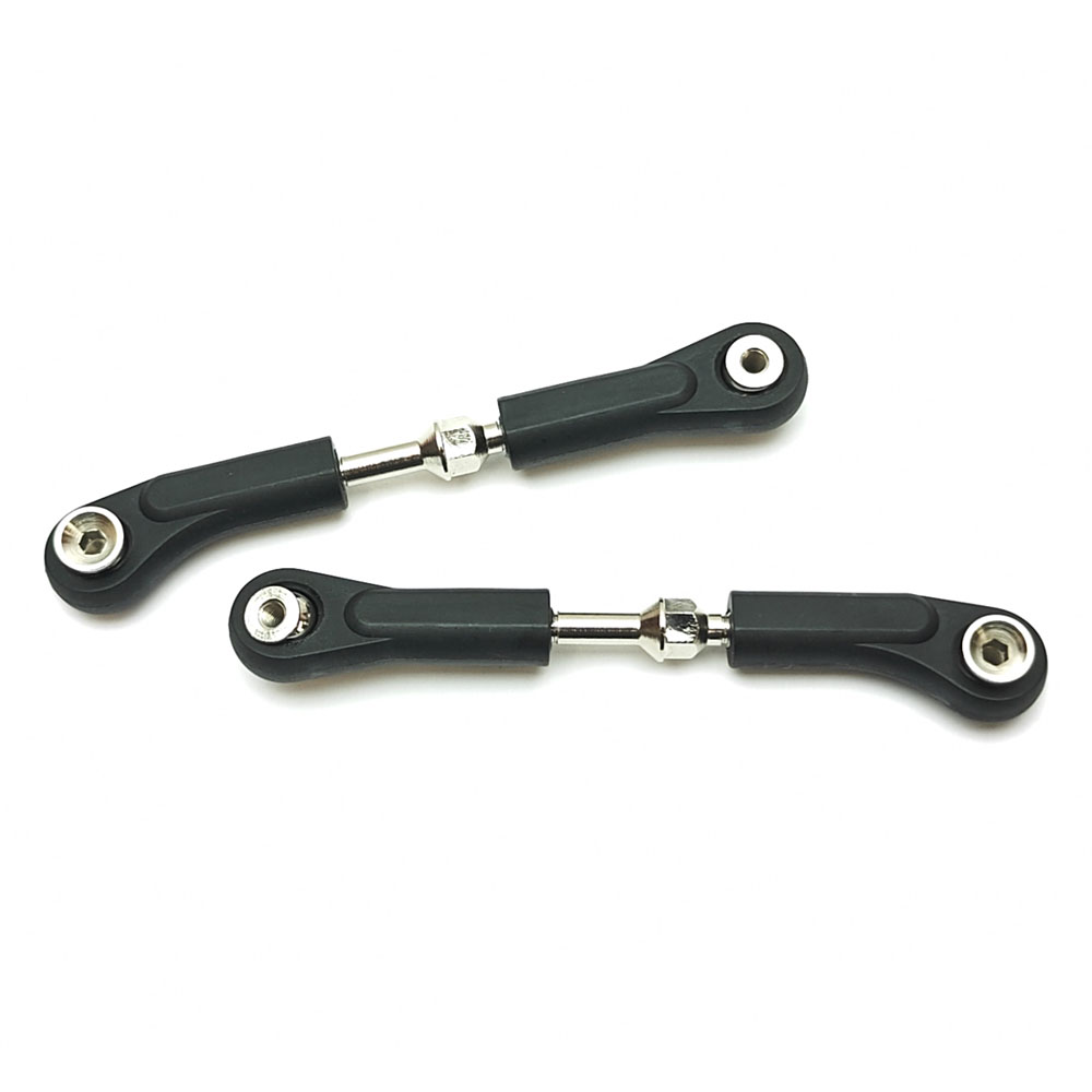
Bag E3 - Front & Rear Hub Assembly
Step 20
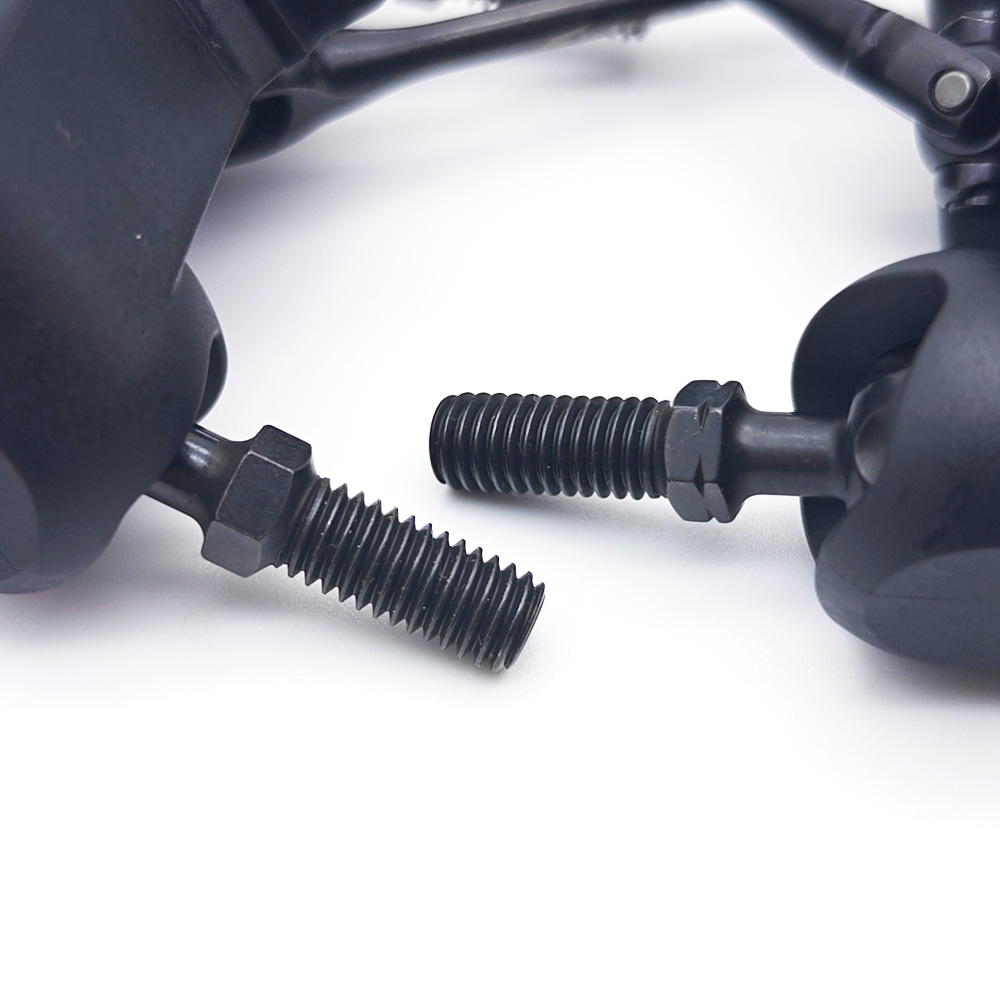
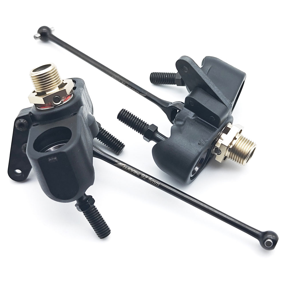
The front steering knuckles are taken directly from the S35-4 Evo, although there isn't much really to improve upon! Do pay attention with the SW338112 Pivot Balls though, as there is an 'L' Left-Hand Anti-Clockwise Thread (Indentation at the hex) and an 'R' Right Hand Clockwise Thread (No indentation). The SW338112L Anti-Clockwise threaded balls (With indentation) must be installed in the Left-Hand-Side steering knuckle as per the image.
Do also take care installing the SW330118A Pivot Ball Retaining Nuts; the thread in the knuckle is very fine and it is very easy to cross thread them, so turn them backwards anti-clockwise first and take your time to make sure its not at an angle.
Step 23-25
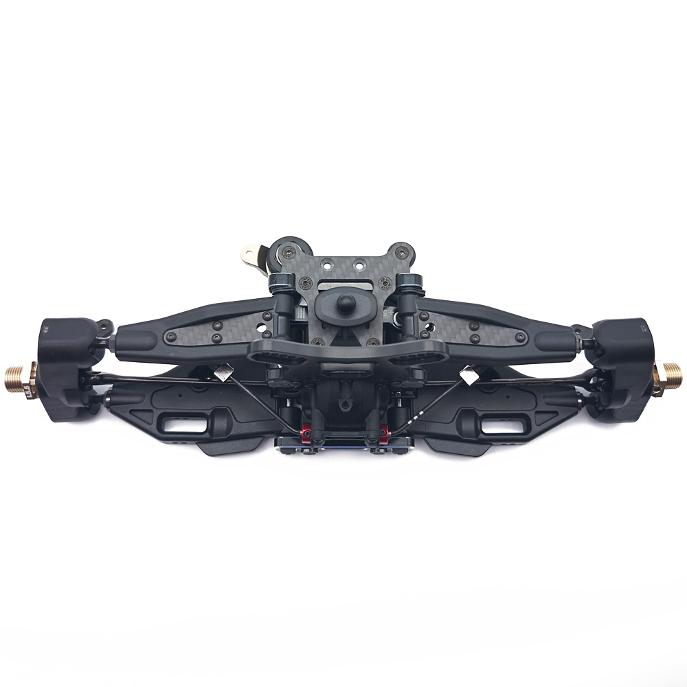
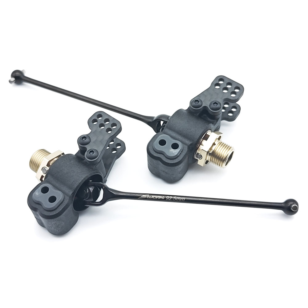
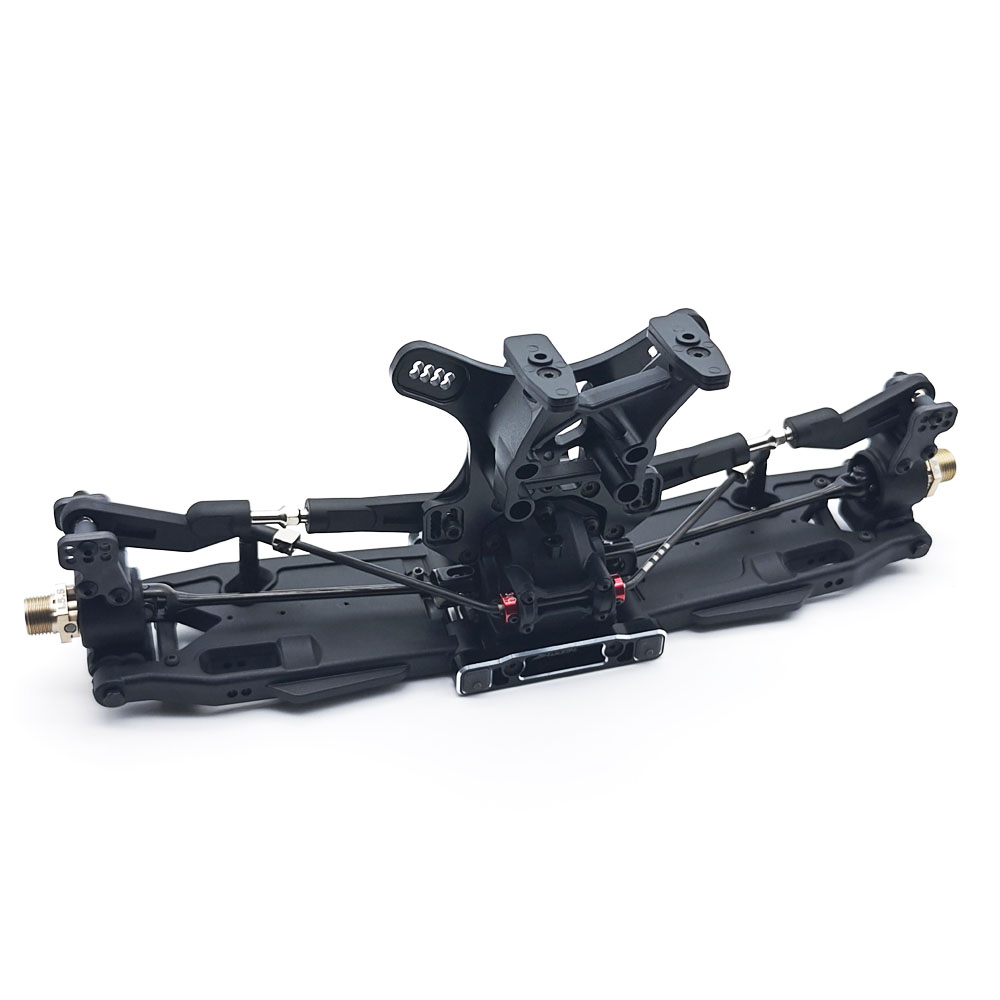
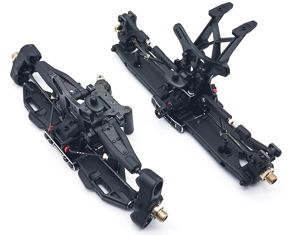
The rear hub carrier assembly again is 90% the same as the S35-4 Evo, but it does feature new carbon adjustment plates which feature optimised roll centre positions, which are the most popular range used by the SWORKz race team.
The inner most hole options from the S35-4 Evo are now gone, but an additional row of outer holes has now been added, this means that the middle column of holes is the same as the standard outer (Longest link) column from the S35-4 Evo, which is arguably one of the most popular setting positions on the car. The option to now run an even longer link on the new outer most hole will also be a very popular option on certain tracks. There is also an additional set of optional (Higher Extension) adjustment plates available as a tuning option; SWORKz S35-5 Series Rear Wheel Hub Adjust Plate (Higher Extension)
To support the overall longer rear camber link, the S35-5 also comes with slightly longer rear upper arm turnbuckles 38mm > 45mm
Bag F - Centre Diff / Chassis Assembly
Step 28
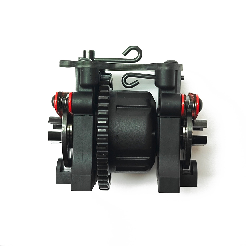
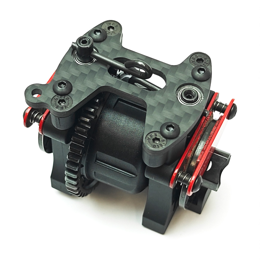
The diagram in this step is slightly wrong - It shows the 2x SW116009 Flanged Bearings being installed in different orientations, but the bearings should be installed as per the front bearing, pushing from underneath the carbon SW348006 Carbon Centre Diff Plate with the flange sitting underneath the top of the plate. The bearings are also quite a snug fit, but this is intentional to ensure that they don't spin inside of the carbon plate, so just ensure the bearings are fully seated to avoid any binding once assembled.
Do also pay close attention to the brake cam levers, one is slightly offset as per the manual which needs to be installed underneath the carbon plate to clear the centre diff housing.
Step 31
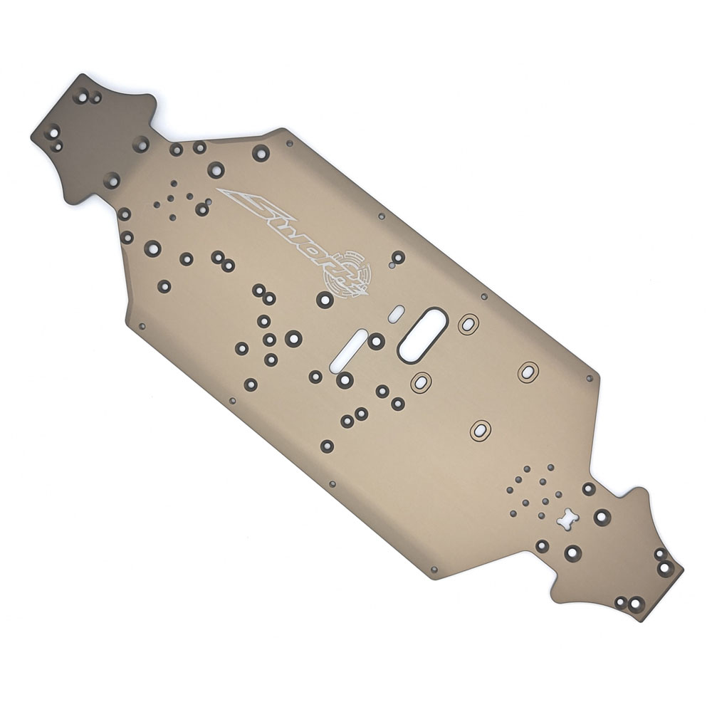
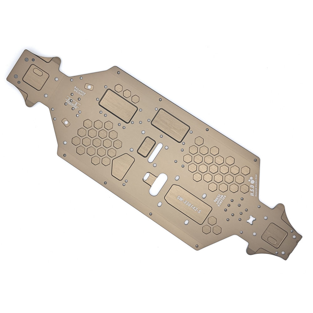
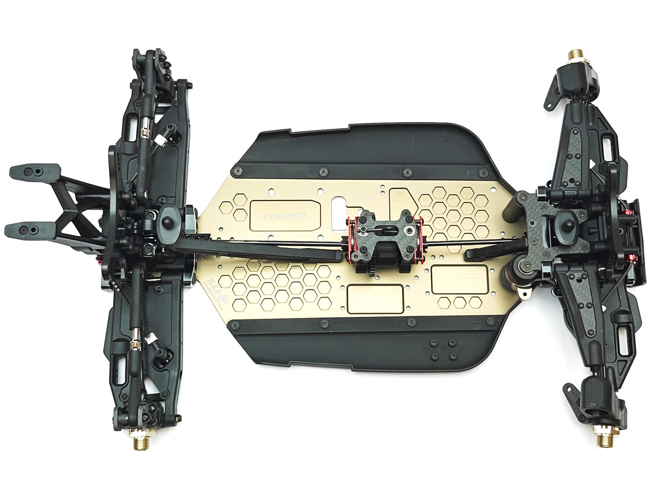
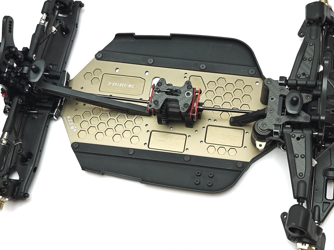
Take your time aligning the complete front end during this step, specifically the bottom of the steering posts which key in to the machining on the chassis plate. If you left the two M3x10 FH screws from the steering assembly loose from Step 18, this will help you rotate them into the correct position before tightening everything down.
Bag G - Radio Tray
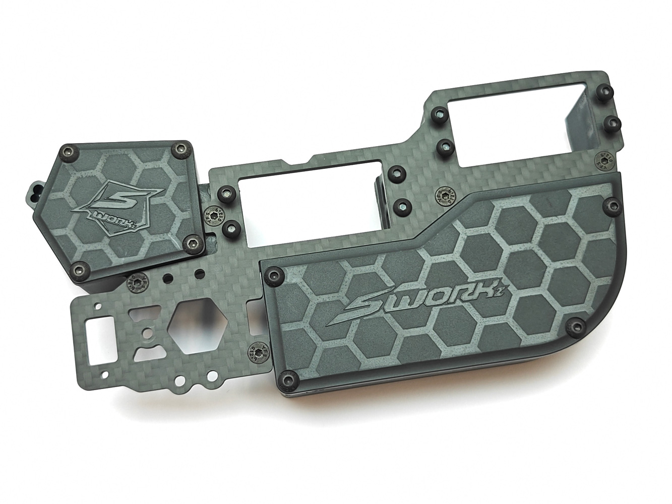
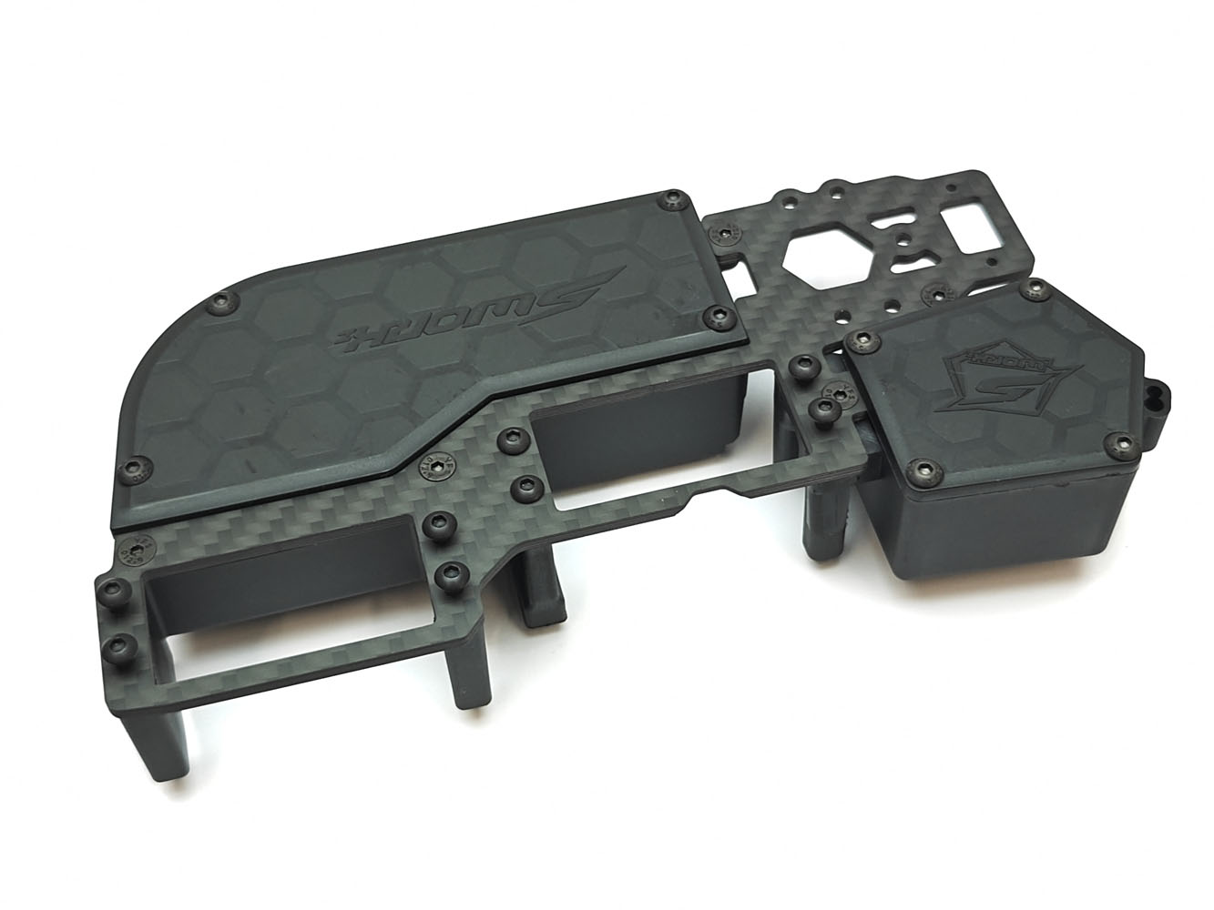
This is another one of the most desired improvements from the previous S35-4 Evo, which has ultimately the same radio tray from the S35-3. Although the old one fundamentally worked, it was lacking when it came to wire routing and also compatibility with switches and transponder placement.. I'm glad to state that those issues are a thing of the past!
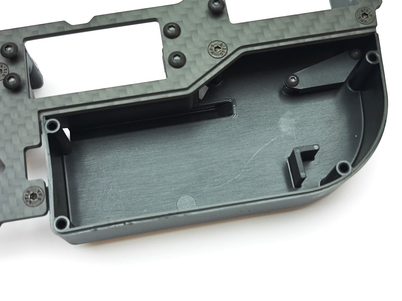
The new radio tray now features a three piece design, a battery compartment/servo holder, a receiver box and now everything is firmly coupled together with a thick and rigid carbon fibre plate. This negates the need to have an optional carbon or aluminium stiffener plate like on the S35-4 Evo. Additionally, the battery box now has internal wire routing for the steering servo, which completely eliminates the risk of damage to the cable. The new design allows mounting of nearly any switch you would desire, be it mechanical or electronic using the transponder mounting holes. Additionally, if you do use the external transponder mounting for an electronic switch, there is a optional forward mounting option for a transponder in the front of the battery compartment.
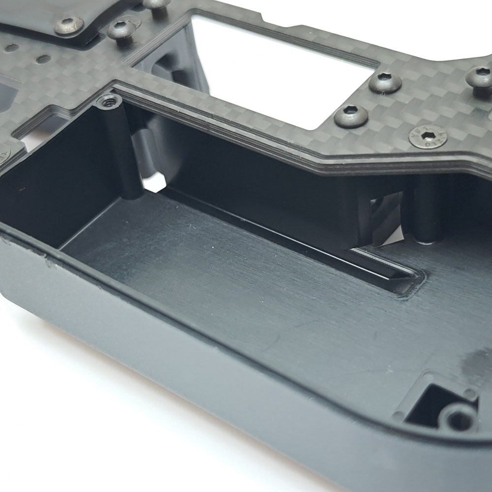
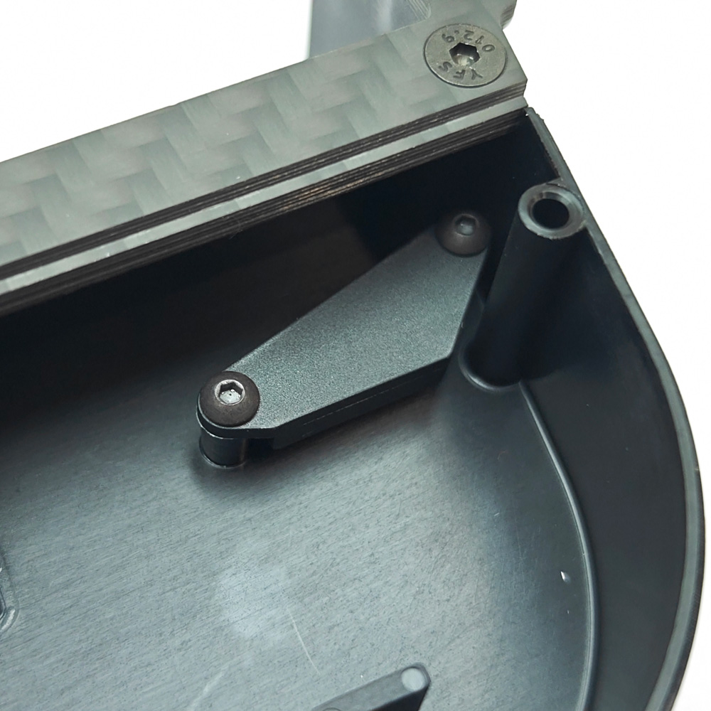
Speaking of the battery compartment, the battery positioning is pretty much the only similarly to the old radio tray, where by the box is designed for use with a 2S 7.2v Li-Ion receiver battery, we carry the TPRO 3000mah 7.2v Li-Ion Receiver Battery Pack which fits perfectly with the supporting tab moulded into the radio box. If you prefer to use a more conventional 2S 7.4v LiPo Stick Pack - You can do this, but you first must remove the plastic tab from inside of the battery compartment using a hobby knife or Dremel.
Bag H - Fuel Tank
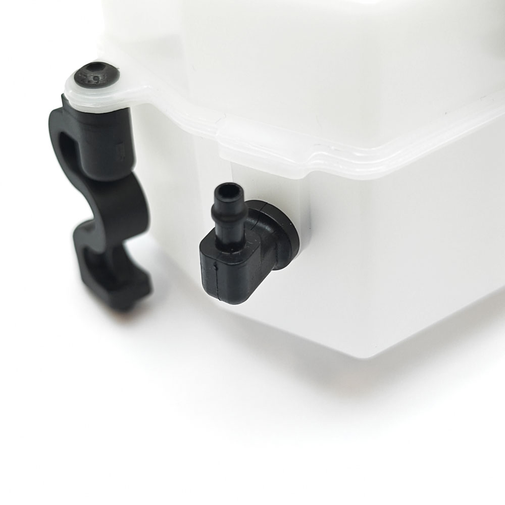
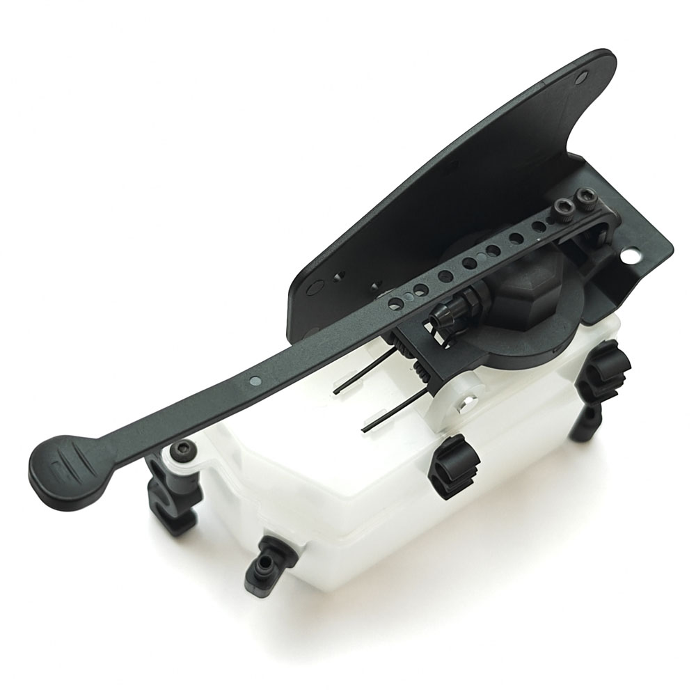
The fuel tank included with the SWORKz S35 is a revised version of the existing SW210033D90 which features a revised fuel nipple design, incorporating an improved internal seal which is significantly more secure than the older tank's design, so a definite improvement yet again. In addition to the fuel nipple, the tank now features the truggy style fuel tank pull as standard, which was preferred by many running the S35-4 Evo, so its great to see this now supplied as standard with the new car.
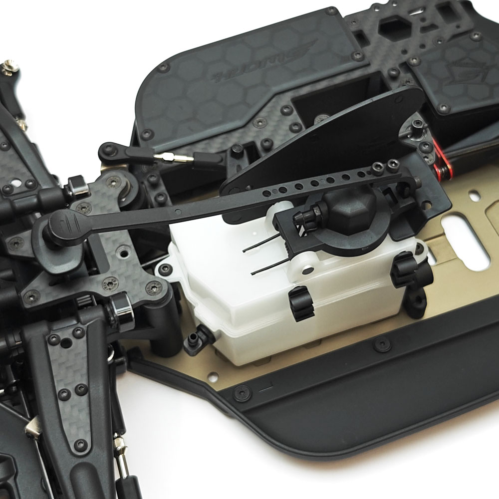
Bag I - Engine Mounting & Clutch Assembly
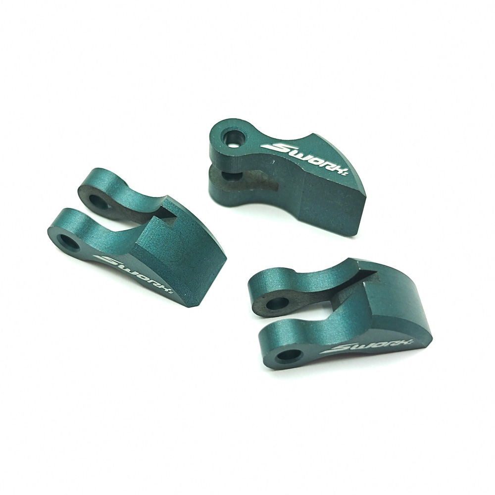
There is now a new 2.0 version of the highly rated SWORKz 'Tornado' clutch shoes. The old ones were liked by many, so it'll be interesting to see how the new ones compare. All we know for now is that the included "Linear" version now feature a new green colour, and that there is an alternative optional 'High Torque' version also available: SWORKz Tornado Clutch Shoes 2.0 (High Torque)
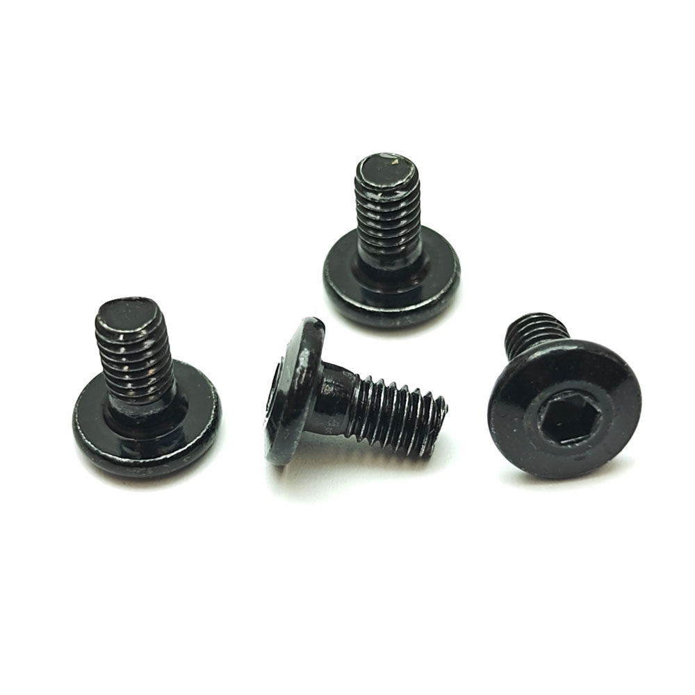
Another issue with older generations of SWORKz 1/8 cars has been the old engine mounting screws, which were always prone to failure due to the low-profile head design.. So we're thrilled to see that SWORKz have now included revised engine mounting screw which has a thicker taper at the based of the head, which should be significantly more durable than the older screws.

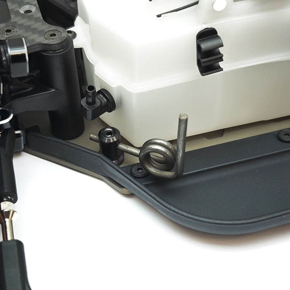
Last but not least, the car also has a new exhaust mount which is a little longer than the older one - But that's not something exciting enough to elaborate on!
Bag J - Throttle Linkage
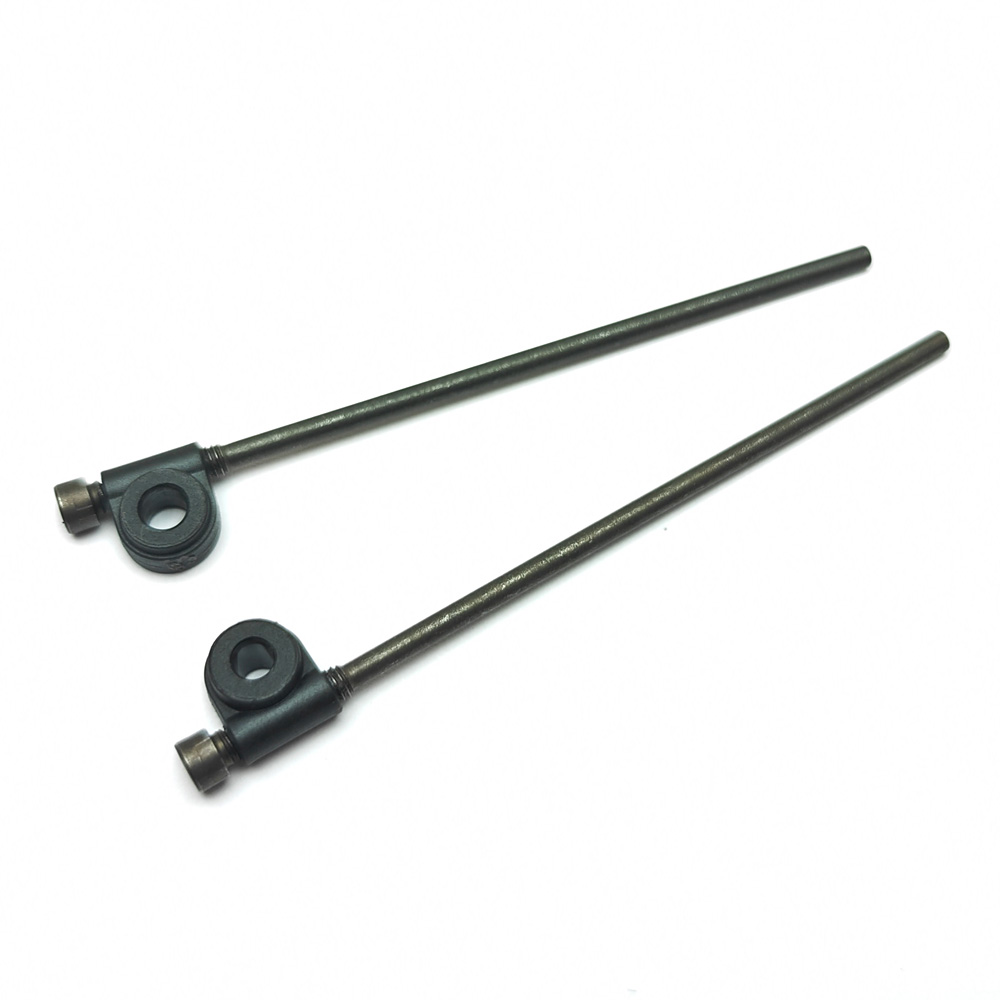
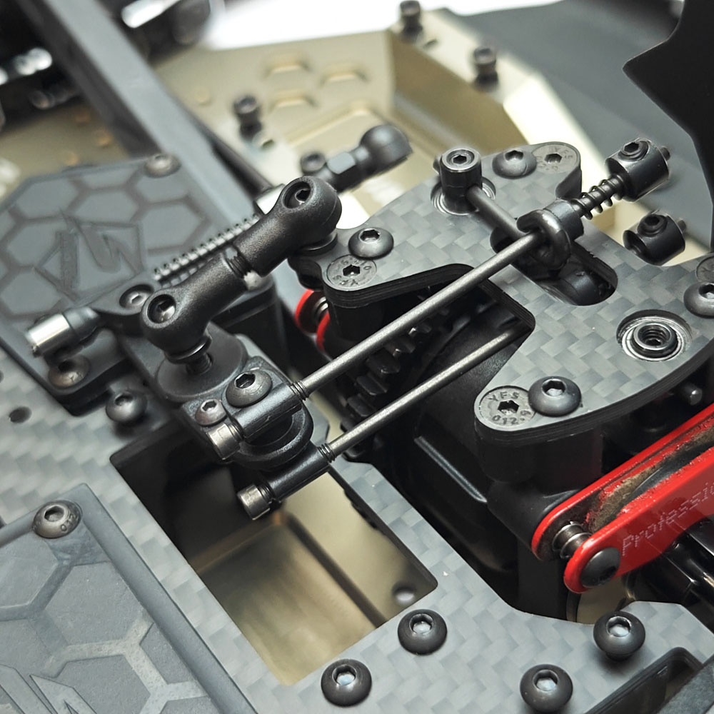
The S35-5 features largely the same throttle linkage setup, and linkages really aren't that exciting.. But we were quite excited to see a significant difference on the brake linkages, which has now done away with the more complicated, more fiddly setup using knurled adjustment collars and replaced both linkage rods with a single piece, 2mm threaded hex head screw, which you can quickly and easily adjust with a hex driver. This is one of those super simple changes that makes you wonder why it hasn't been done before, but we're sure now that SWORKz have, it won't be long before others follow suit and it becomes an industry standard.
Step 50
The S35-5 comes included with the adjustable linkage brace from the S35-4 Evo, this helps to reinforce the radio tray by screwing directly into the throttle servo, which significantly reduces flex during heavy braking to give a more positive braking feel. There isn't a specific length for it in the manual as you need to adjust the length to suit the servo and/or placement of it in the radio tray, so just take your time to adjust it to the correct length to easily attach it to the servo without force.
Bag K - Shock Absorbers
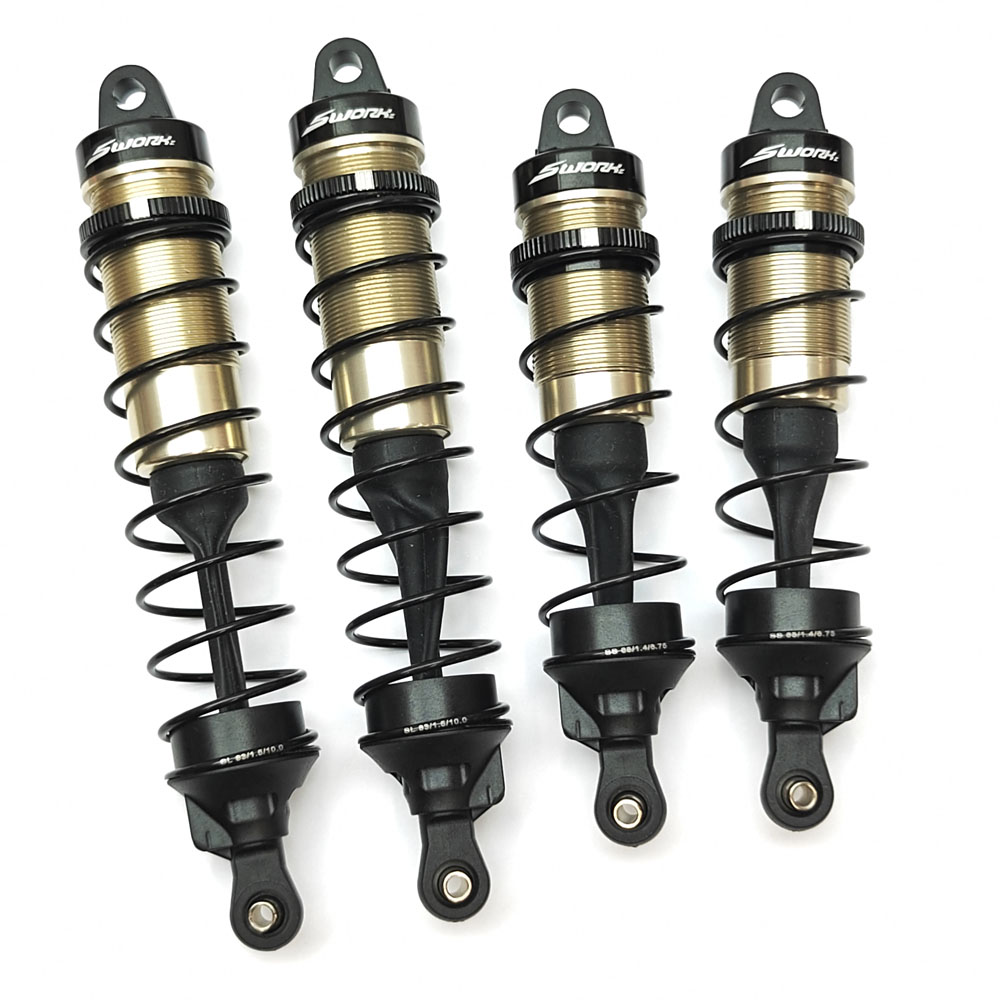
The shocks feature a few notable improvements over the S35-4 Evo, namely a revised 'B' spec shock shaft which features a slightly longer threaded section for the M2 piston retaining nut, this should give better surface area for the nyloc ensuring it doesn't come loose as easily. This extra length would also be beneficial with aftermarket shock pistons, which can have a thicker profile.
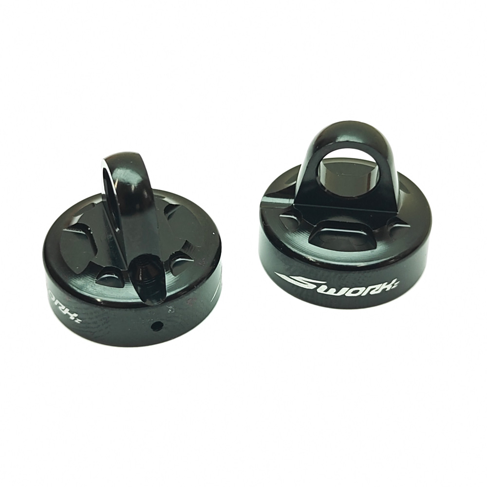
The shocks also have a new shock cap; similar to the older cap from the S35-4 Evo in that it can be built either with a hex-cell shock bladder or emulsion seal, of which you have both options included in the kit, so you can build them depending on preference.
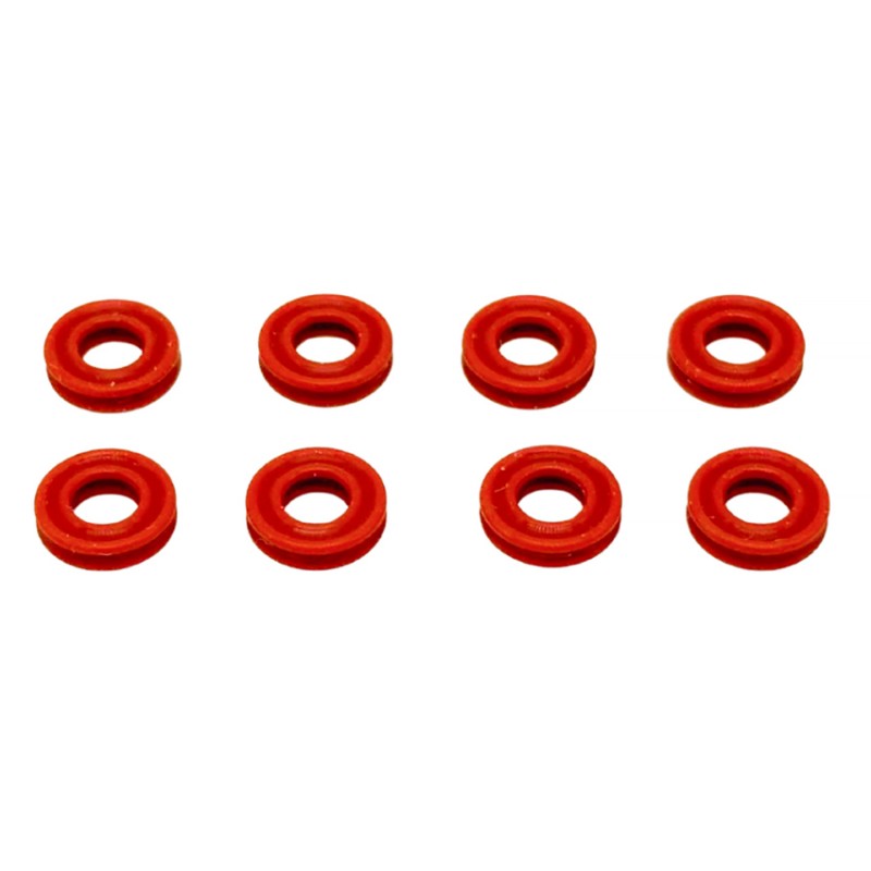
Also revised is a new lower shock ring seal, which now features a new 'X Ring' seal similar to that spec'd with the SWORKz S12-3 1/10 buggy. The X-Ring seals should provide a better seal with similar, if not reduced friction which should further improve the shock damping.
Lastly, another great addition is the new SWORKz 'Samurai' Shock Springs, which we've now come to learn are essentially HB Shock Springs, which are rated by many as being some of the best spec shock springs on the market, adopted by many other team drivers of many other makes and models of 1/8 buggy. These were a very popular option for many SWORKz team drivers, so the fact that SWORKz have managed to source them to include with the kit is another big win! In recent months we've stocked the Infinity springs, which again are the same springs. The S35-5 comes as standard with a 6.75 (SS-4 Dot) front spring and a 10 (SL-3 Dot) rear spring. For optional tuning there is also a SWORKz S35-5 Samurai 6.25 (SS-5 Dot) Front Spring Set and SWORKz S35-5 Samurai 9.5 (SL-4 Dot) Rear Spring Set available separately, both of which are stiffer than the standard springs. We hope that SWORKz will expand the range of the Samurai springs in the future to include some more we know do exist.
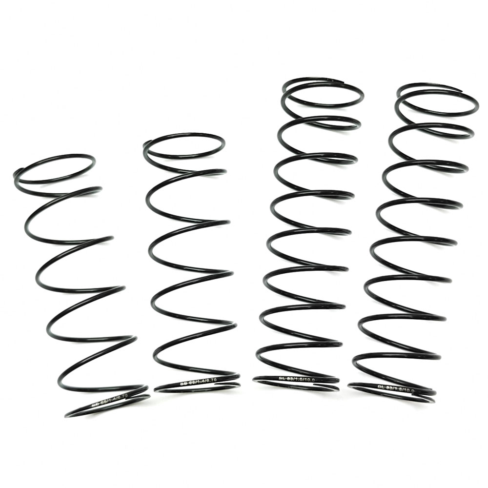
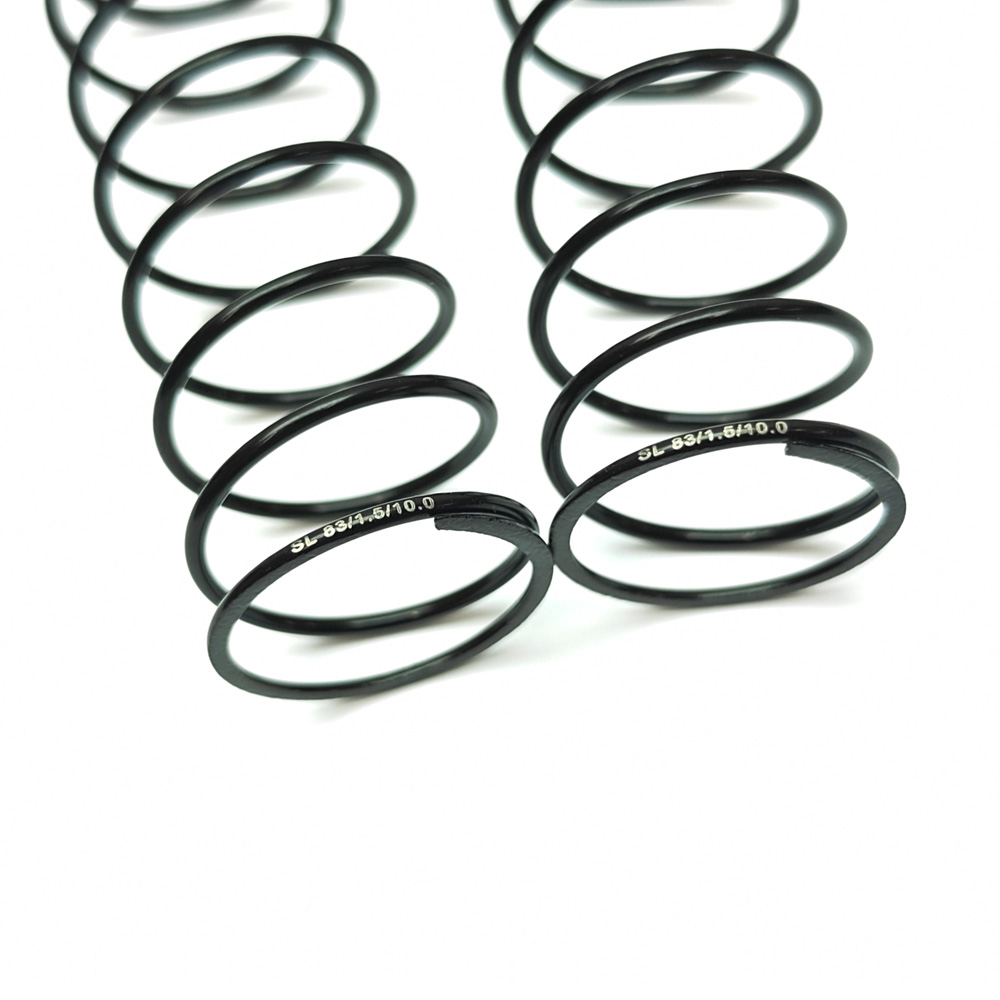
| Reference | Description | Rating | HB Equivalent | |
| Front Springs | ||||
| SW118007-5 | Samurai Competition Front Shock Spring (SS-5 Dot) (68 X 1.4 X 6.25 ) | Hard | Option | Gold |
| SW118007-4 | Samurai Competition Front Shock Spring (SS-4 Dot) (68 X 1.4 X 6.75 ) | Medium | Standard | Yellow |
| Rear Springs | ||||
| SW118008-4 | Samurai Competition Rear Shock Spring (SL-4 Dot) (83 X 1.5 X 9.5) | Medium | Option | Yellow |
| SW118008-3 | Samurai Competition Rear Shock Spring (SL-3 Dot) (83 X 1.5 X 10.0) | Soft | Standard | Blue |
We built the shocks up with some XTR 500 CPS oil in the front and some XTR 450 cps in the rear, although you do get some SWORKz branded 600 CPS oil. Whichever way you go with the choice of oil, the shocks built up like a dream and felt buttery smooth!
Step 54
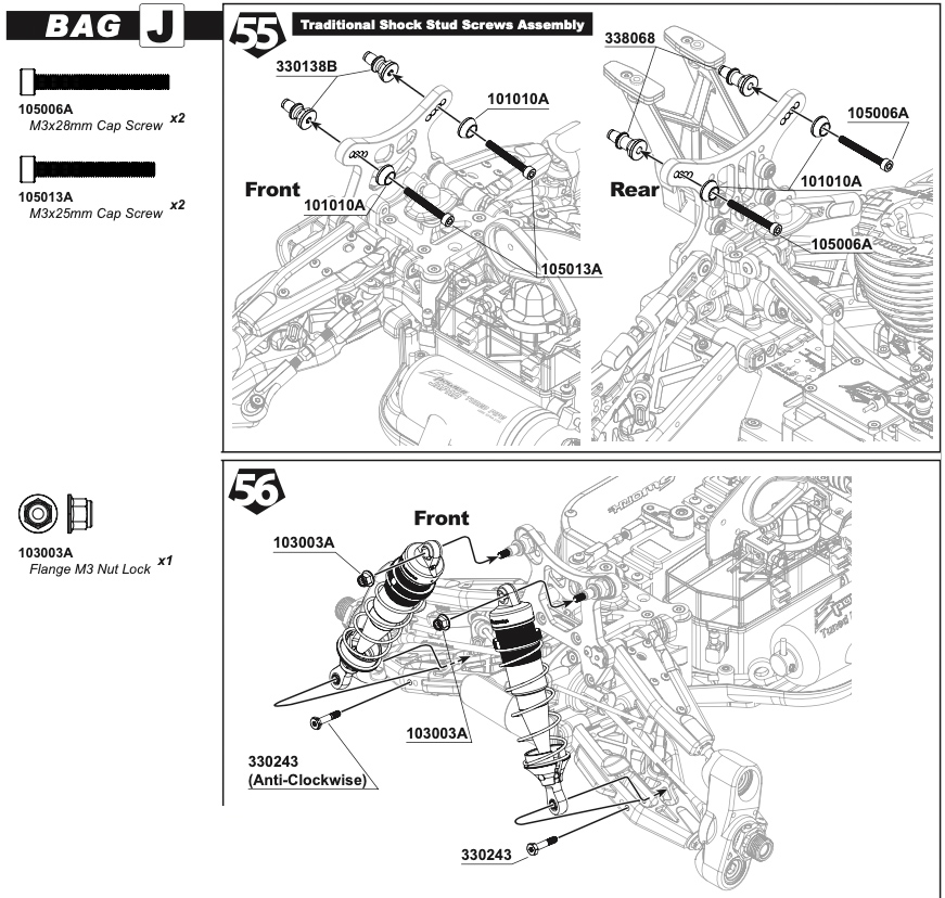
The older S35-4 Evo manual used to show two methods of mounting the shocks; a fully captured setup using a long M3 screw and nyloc nut OR a non-captured design using shorter screws at either end. Frustratingly the manual only now shows the non-captured setup, although you DO get the all the hardware to mount them in the captured configuration; which is our preferred method as it gives the best reliability.
Here is an exert of the captured setup from the S35-4 Evo manual to help if you prefer to do this also:

Step 56
The lower shock retaining screws are the same as previous generations, so you get 2x left-hand anti-clockwise thread and 2x normal clockwise thread screws. The silver ones are the left-hand anti-clockwise thread, which are the ones to be installed on the left hand side arm looking from either end of the car - It would be handy if the manual did also state the colour to save you figuring it out!
Bag L - Air Filter
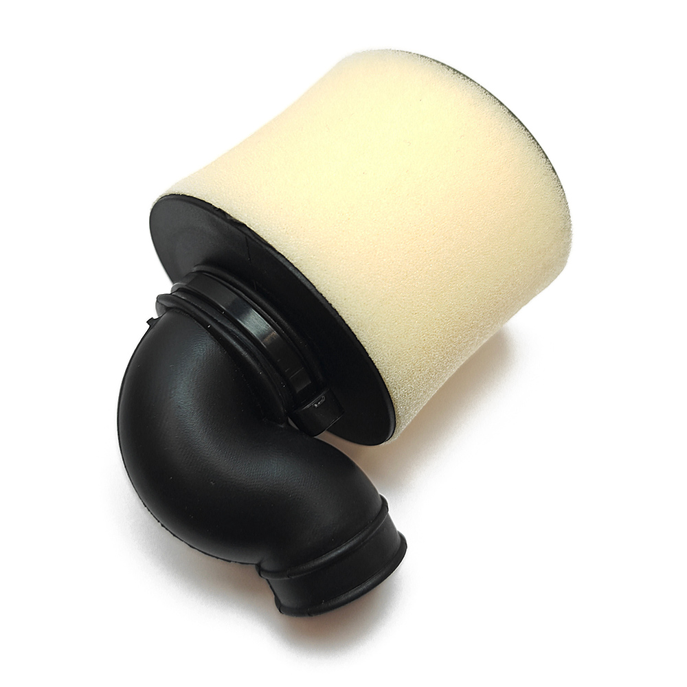
Another small change to the S35-5 is the inclusion of an old-school 90-degree type air filter elbow, rather than the cab-mounted forward position elbow form the S35-4 Evo. This shorter elbow is thought to give slightly better performance form the engine given the shorter distance.
Bag N - Wing & Bodyshell
Further increasing the value-for-money of the S35-5, the kit now includes the preferred 'Pro Race Wing' which is a much more modern style wing giving a better downforce profile more akin to modern 1/8 buggy racing, so its great that its now included as standard spec like many new additions to the car. We finished off the wing installation with our own branded RC-Project Wing Washer - Of course; it had to be Red!
The last piece of the puzzle to the S35-5 is the new Falcon ST-5 body, which whilst at first glance did not look too dissimilar from the older Falcon ST-4 body, it does feature some choice changes in shape which contribute to improving the handling characteristics of the S35-5 into and out of the corners.
Complete!
We hope you found this build blog interesting and at least useful when it comes to building your own S35-5 kit. We are genuinely really excited for this new chapter for the S35 series car and can't wait for you all to receive your kits and enjoy the success with them at the track.
If you need any support with your kit, or anything at all, please don't hesitate in reaching out to us.
Tel: (+44) 01772 626 777
E-Mail: sales@answer-rc.com